A Numerical Set-up For Benchmarking And Optimization Of Fluid-Structure Interaction
The objective of this benchmark is to test and compare different numerical approaches for fluid-structure interaction (FSI) and code implementations with respect to efficiency and accuracy of the computation, and to extend these validated configurations to different optimization problems. This FSI benchmark is based on an older successful ’flow around cylinder’ benchmark for incompressible laminar fluid flow (Schäfer and Turek, 1996). Similar to this older configuration, here the flow is considered to be incompressible and in the laminar regime. The structure is allowed to be compressible, and the deformations of the structure should be significant. The overall setup of the interaction problem is such that the solid object with an elastic part is submerged in a channel flow.
Requirements: meshing, FSI solver and optimizer software, 2D, laminar regime
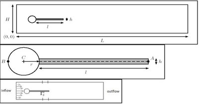
Computational domain: The domain is shown here in Figure 1.
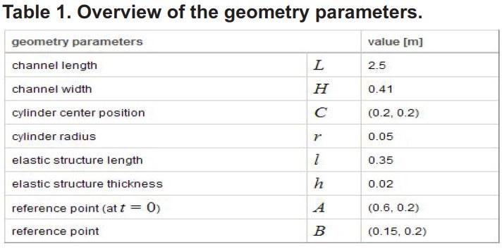
Geometry parameters:

- The setting is intentionally non-symmetric to prevent the dependence of the onset of any possible oscillation on the precision of the computation.
- By omitting the elastic bar attached with the cylinder one can exactly recover the setup of the well known flow around cylinder benchmark configuration which can be used for validating the CFD part.
- The control points are A(t), fixed with the structure with A(0)=(0602), and B=(01502).
Modeling: physical properties:
- Incompressible Newtonian fluid (Navier-Stokes)
- Elastic compressible solid (St. Venant-Kirchhoff material)

Boundary and/or initial conditions for computations:
Boundary conditions:
A parabolic velocity profile is prescribed at the left channel inflow

such that the mean inflow velocity is U and the maximum of the inflow velocity is 1.5U.
- The outflow condition can be chosen by the user, for example stress free or do nothing condi-
tions.
- The no-slip condition is prescribed for the fluid on the other boundary parts i.e. top and bottom
wall, circle and fluid structure interface 
Initial conditions:
Suggested starting procedure for the non-steady tests is to use a smooth increase of the velocity profile in time
Optimization:
Lift reduction under variation of geometrical design variables and boundary control.
Design parameters:
- Boundary control
Objective function definition:

Results:
Quantities of interest
- Table, three mesh levels
- The position of the end of the structure, displacement in x y directons, drag and lift, V1 and V2
additionally Number of equations, number of iterations, and CPU time.
- Forces exerted by the fluid on the whole body ( lift and drag forces acting on the cylinder and
the structure together
- Frequency and maximum amplitude (for nonstationary tests)
Stationary without and with optimization:
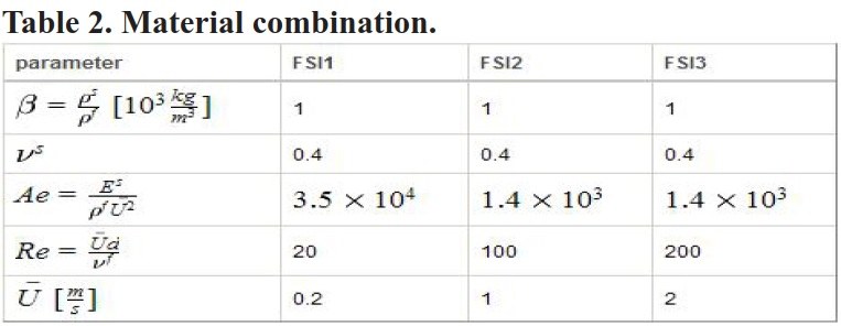
- Produce FSI1, CFD1, CSM1 (see attached pdf file)
- FSI1 and FSI1 example1 (see table of example 1 in ppt file attached)
- Minimum lift values in case of optimization
Nonstationary without optimization
- Check your code on FSI2 and FSI3
Suggestions
- Validate your FSI code without optimization
- FSI1 + Ex1 send us results untill summer
- Preliminary test for other examples untill fall
pressure loss minimize: minimize(P in−P out) w.r.t elastic deformation of the wall or geometri-
cal and material properties of the beam
-
Defined by Stefan Turek & Mudassar Razzaq, 2006
