Shock Control Bump Optimization on a Transonic Laminar Flow Airfoil
Drag reduction for transonic wings is crucial for the aeronautical industry, for control of aviation emission and operational efficiency. Shock control bumps were found to be effective in reducing the wave drag and the total drag if installed on transonic airfoils or wings. However, their effectiveness relies on the position,
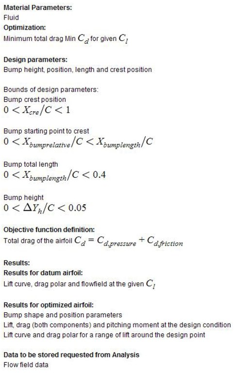
height, and size of the bumps. In this test case, we will look into the optimal design parameters for a given laminar flow airfoil, i.e. RAE5243 airfoil, at the design Mach number and Reynolds number. It will be divided into two cases: (1) fully turbulent flow; (2) fixed transition at 45%c. The optimization will be constrained by the given lift condition.
Requirements:
Navier-Stokes flow solver with turbulence modelling
Optimization method with lift constraint
Computational domain:
Figures 1 and 2 below show the airfoil, the bump and its parameterisation. The computational domain is suggested to be 20 chord length away from the airfoil in all directions.
Modeling: physical properties:
Air as perfect gas
Laminar or turbulent flow (fixed transition)

Boundary and/or initial conditions for computations:
Steady state solution
No-slip boundary condition at wall and far field boundary condition
Fully turbulent or fixed transition

-
Defined by Ning Qin, 2006.
